Specifically, I'm trying to add an auxiliary input (for MP3s and iPods and such) to a really old boombox.
I've removed all the circuit boards from the boombox itself, and the PCB for tuning was damaged in the process, so I'm unsure if it is still usable.
Anyway, the model is the Sanyo MCD-Z2F(K), which had a CD-player, cassette player and AM/FM radio, and required 12V DC power supply. The CD player's laser is unusable (not sure why) and I was hoping that I would be able to replace the CD player with the auxiliary input. Any and all help is appreciated, though any links to stores will be disregarded seeing as I'm in Australia, and American stores are a bit too far to be of any help.
(I hope this is in the right place...)
Boombox modification
Moderator: Moderators
-
tony1695

- Weaver of Tales
- Posts: 5738
- Joined: Wed Jul 28, 2010 5:49 am
- Location: POOTISPOOTISPOOTISPOOTIS
Boombox modification
Gentlementlemen
How do you get to the Rakdos Guild Hall?
You take the psycho path.
Weed la Weed Warning: WEIRD
How do you get to the Rakdos Guild Hall?
You take the psycho path.
Weed la Weed Warning: WEIRD
-
cliffpanther

- Grand Templar
- Posts: 1328
- Joined: Thu Jun 17, 2010 3:47 pm
- Location: In the central point of the Universe. Just like everyone else.
Re: Boombox modification
Okaaay, could you upload a photo of that boombox, I'd really like to see how the CD player is connected to the rest of it - unluckily, I wasn't able to find any schemes online...
AUX input sockets should be available in most of electronics shops.
AUX input sockets should be available in most of electronics shops.
Greetings!
Amazing art drawn by an amazing Artist
Amazing art drawn by an amazing Artist
-
tony1695
- Weaver of Tales
- Posts: 5738
- Joined: Wed Jul 28, 2010 5:49 am
- Location: POOTISPOOTISPOOTISPOOTIS
Re: Boombox modification
Right. Sorry.


Anyway, the first one is everything I have that's still usable. I had to cut the cassette player and tuner loose to get everything else out. The fourth one is the actual CD player circuitry, and the last one is the Power supply. I still have the cable, which is good seeing I had to cut off the battery cables.
Anyway, the first one is everything I have that's still usable. I had to cut the cassette player and tuner loose to get everything else out. The fourth one is the actual CD player circuitry, and the last one is the Power supply. I still have the cable, which is good seeing I had to cut off the battery cables.
Gentlementlemen
How do you get to the Rakdos Guild Hall?
You take the psycho path.
Weed la Weed Warning: WEIRD
How do you get to the Rakdos Guild Hall?
You take the psycho path.
Weed la Weed Warning: WEIRD
-
cliffpanther
- Grand Templar
- Posts: 1328
- Joined: Thu Jun 17, 2010 3:47 pm
- Location: In the central point of the Universe. Just like everyone else.
Re: Boombox modification
http://img148.imageshack.us/img148/2435/dscf1755o.jpg
I think this is the CD player circuit, right (The fourth one looks more like tape one)? Well, it will be sightly complicated - I hope you have soldering iron, because you will not make it without one. You have to find out which cables are responsible for which tracks, and where's the ground - it is probably connected to an integrated circuit - tell me what model is it.
I think this is the CD player circuit, right (The fourth one looks more like tape one)? Well, it will be sightly complicated - I hope you have soldering iron, because you will not make it without one. You have to find out which cables are responsible for which tracks, and where's the ground - it is probably connected to an integrated circuit - tell me what model is it.
Greetings!
Amazing art drawn by an amazing Artist
Amazing art drawn by an amazing Artist
-
tony1695
- Weaver of Tales
- Posts: 5738
- Joined: Wed Jul 28, 2010 5:49 am
- Location: POOTISPOOTISPOOTISPOOTIS
Re: Boombox modification
Whoops. I meant the fourth one is the CD player itself. And you are right, that link is the circuitry.cliffpanther wrote:http://img148.imageshack.us/img148/2435/dscf1755o.jpg
I think this is the CD player circuit, right (The fourth one looks more like tape one)?
As for the model, refer to the first post.
And as for a soldering iron, this is my Electronics and Robotics project, so I have access to everything I need, from solder to transistors to reams of colourful wire.
Gentlementlemen
How do you get to the Rakdos Guild Hall?
You take the psycho path.
Weed la Weed Warning: WEIRD
How do you get to the Rakdos Guild Hall?
You take the psycho path.
Weed la Weed Warning: WEIRD
-
cliffpanther
- Grand Templar
- Posts: 1328
- Joined: Thu Jun 17, 2010 3:47 pm
- Location: In the central point of the Universe. Just like everyone else.
Re: Boombox modification
You got me wrong... I didn't mean Boombox model. I meant the integrated circuit, which lookes likr this:
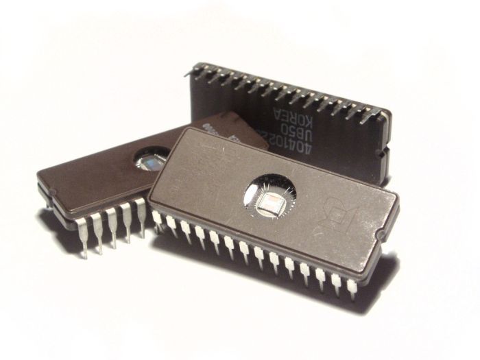
You have to see where input signal from CD player goes to. I need the model (and maybe s/n), to see where you need to solder the cables for aux.
You have to see where input signal from CD player goes to. I need the model (and maybe s/n), to see where you need to solder the cables for aux.
Greetings!
Amazing art drawn by an amazing Artist
Amazing art drawn by an amazing Artist
-
tony1695
- Weaver of Tales
- Posts: 5738
- Joined: Wed Jul 28, 2010 5:49 am
- Location: POOTISPOOTISPOOTISPOOTIS
Re: Boombox modification
AH, I see.
Well, the IC has this printed on it:
(Top line) Sanyo 2B4
(Bottom line) LC66406A 4879
Is that what you need?
Well, the IC has this printed on it:
(Top line) Sanyo 2B4
(Bottom line) LC66406A 4879
Is that what you need?
Gentlementlemen
How do you get to the Rakdos Guild Hall?
You take the psycho path.
Weed la Weed Warning: WEIRD
How do you get to the Rakdos Guild Hall?
You take the psycho path.
Weed la Weed Warning: WEIRD
-
cliffpanther
- Grand Templar
- Posts: 1328
- Joined: Thu Jun 17, 2010 3:47 pm
- Location: In the central point of the Universe. Just like everyone else.
Re: Boombox modification
Yes, thank you. Now, gimme a sec, I need to check it. And if I don't find it, I will ask a friend who knows most of circuit specifications...
Greetings!
Amazing art drawn by an amazing Artist
Amazing art drawn by an amazing Artist
-
avwolf

- Templar Inner Circle
- Posts: 7006
- Joined: Wed Jan 17, 2007 5:33 pm
- Location: Nebraska, USA
- Contact:
Re: Boombox modification
Your PCB has a lot of the "diagramming" done on it already. See all the little words printed by connectors and wires? You're really not interested in splicing into the DSP that handles the the CD translation; you're actually interested in splicing in after it's done, since you're replacing it. The photos aren't zoomed in or clear enough for me to read, but do you have indications of what the connections are between the darker colored board and the lighter colored board with the DSP on it?